In an interconnected digital workstation or high-refresh-rate gaming setup, your computer monitor is the visual window into everything you accomplish. Whether you are editing color-graded 4K video, crunching financial spreadsheets across multiple displays, or immersing yourself in competitive gaming, video signal reliability is paramount. Yet, one of the most physically vulnerable components on any modern display is the humble female HDMI (High-Definition Multimedia Interface) port. Because HDMI cables are stiff, heavy, and frequently plugged, unplugged, or angled behind cramped desks, physical port failure is among the most widespread hardware faults technicians encounter. In this definitive guide to hdmi port repair, our certified bench engineers break down how monitor HDMI ports work, why they fail, how to diagnose hidden pin damage, the intricate micro-soldering process required to replace them, and when repair makes economic sense over purchasing a replacement screen.
In This Comprehensive HDMI Port Repair Guide
- The Anatomy of an HDMI Port: 19 Pins of High-Speed Micro-Engineering
- Why Monitor HDMI Ports Break: The Top 5 Failure Vectors
- Top Symptoms of a Damaged or Failing Monitor HDMI Port
- Step-by-Step Diagnostic Protocol: Is It the Cable, GPU, or Port?
- Inside the Professional Micro-Soldering HDMI Port Repair Process
- Handling Torn Circuit Traces: Micro-Jumper Reconstruction
- HDMI Version Standards: Bandwidth, Refresh Rates & Compatibility
- Monitor Repair vs. Replacement: The Financial & Environmental Equation
- Temporary Workarounds: Adapters, DisplayPort & USB-C Alt-Mode
- Preventative Care: 5 Ways to Protect Your Display Ports from Physical Strain
- Why Choose DC Phone Repair for Your Monitor Board Repairs
The Anatomy of an HDMI Port: 19 Pins of High-Speed Micro-Engineering
To understand why hdmi port repair requires specialized precision equipment rather than simple at-home glue or pliers, one must first appreciate the intricate electrical architecture packed into a standard Type-A HDMI receptacle. Measuring just 13.9 millimeters wide and 4.45 millimeters high, this compact metallic jack houses exactly 19 microscopic conductive contact pins, each assigned to dedicated high-frequency differential signaling pairs or low-voltage communication buses:
| Pin Number | Pin Assignment Name | Critical Electrical Function |
|---|---|---|
| Pins 1, 3 | TMDS Data 2+ / Data 2- | Transition-Minimized Differential Signaling: Carries Blue video color channel data and audio packet multiplexing. |
| Pins 4, 6 | TMDS Data 1+ / Data 1- | Carries Green video color channel data and audio timing synchronization. |
| Pins 7, 9 | TMDS Data 0+ / Data 0- | Carries Red video color channel data and high-speed packet framing. |
| Pins 10, 12 | TMDS Clock+ / Clock- | Carries the master pixel clock reference signal; critical for raster frequency synchronization. |
| Pins 2, 5, 8, 11 | TMDS Data & Clock Shields | Ground isolation barriers designed to prevent electromagnetic interference (EMI) and crosstalk between gigabit data channels. |
| Pin 13 | CEC (Consumer Electronics Control) | Bi-directional command bus enabling remote controls and unified power on/off commands across connected audio/video hardware. |
| Pins 15, 16 | SCL (DDC Clock) / SDA (DDC Data) | I2C communication channel transmitting EDID (Extended Display Identification Data) metadata—communicates monitor model, native resolutions, and refresh rates to the graphics card. |
| Pin 18 | +5V Power Delivery Rail | Supplies low-voltage power from the video transmitter to power the monitor's EDID EEPROM chip even when the display is in deep standby. |
| Pin 19 | Hot Plug Detect (HPD) | Signals the graphics card that a physical cable connection is made, triggering the cryptographic HDCP handshake and video stream generation. |
These 19 microscopic pins terminate at the rear of the port housing onto tiny surface-mount copper pads on the monitor's video scaler motherboard, spaced with a microscopic pitch of merely 0.5 millimeters. If even a single pin is bent, bridged, or lifted from the printed circuit board (PCB), the entire digital video pipeline collapses.
Why Monitor HDMI Ports Break: The Top 5 Failure Vectors
While computer monitors can operate reliably for a decade or more, their input ports are subject to constant mechanical, thermal, and electrical stressors. In our repair facility, we find that the vast majority of broken HDMI ports stem from one of five primary root causes:
1. Leverage-Induced Torque & Cable Tension
Premium braided HDMI 2.1 cables are thick, stiff, and heavy due to multi-layer shielding and heavy copper wiring. When a monitor is pushed closely against an office wall, mounted on an articulating gas-spring monitor arm, or adjusted for height and tilt, the rigid cable acts as a mechanical lever. A gentle tug on a 6-foot cable translates into tremendous torque force focused directly onto the four through-hole mounting anchor tabs holding the port to the PCB. Over time, these solder anchors fracture, causing the port to wobble and eventually snap the delicate surface-mount signal pins underneath.
2. Accidental Tripping & Violent Cable Snags
A running pet, an active child, or a worker catching their foot on a dangling HDMI cord running between a desktop tower and desk can impart an instantaneous shearing force. When snagged violently, either the HDMI cable head snaps off inside the monitor housing, or the entire internal female receptacle is ripped directly off the video scaler board, frequently tearing the delicate copper circuit traces clean off the fiberglass PCB substrate.
3. Upside-Down or Misaligned Insertion Force
Unlike symmetrical reversible connectors like USB Type-C, the standard HDMI Type-A connector is keyed with an asymmetrical trapezoidal profile. In dim lighting behind a monitor, users frequently attempt to force an HDMI cable in upside-down or at an extreme angle. Forcing the connector crushes the delicate central plastic guide tongue inside the port, bending the 19 gold-plated spring pins inward into an irreparable tangled mesh or snapping the plastic tongue entirely.
4. Wear-and-Tear from Chronic Hot-Plugging
Modern hybrid professionals frequently move laptops between workstations, plugging and unplugging their primary display cables multiple times daily. Standard consumer HDMI receptacles are rated by manufacturers for approximately 5,000 to 10,000 insertion cycles under optimal perpendicular alignment. Repeated off-axis insertions gradually scrape away the microscopic 30-microinch gold plating on the contact fingers, exposing underlying nickel and phosphor-bronze alloys to oxidation, causing signal degradation and intermittent connection loss.
5. Electrostatic Discharge (ESD) & Ground Loop Surges
Modern monitors operate high-speed differential transmitters sensitive to electrical over-stress. Walking across carpet in low-humidity environments can charge a human body to over 15,000 volts of static electricity. Touching an ungrounded HDMI cable tip directly into the metal shell can discharge static into the monitor's Hot Plug Detect or DDC lines, blowing the surface-mount ESD protection clamping diodes or frying the main scaler integrated circuit (IC).
Top Symptoms of a Damaged or Failing Monitor HDMI Port
HDMI port failure does not always manifest as an abrupt, permanent black screen. Often, micro-fractures in solder joints or partially bent pins generate subtle intermittent symptoms that worsen over weeks:
- The "Wiggle Test" Dependency: The most universal indicator of physical port failure. The screen stays completely dark until you manually press, push upward, or wedge the HDMI cable at a specific angle. This indicates that one or more through-hole solder joints have cracked, breaking electrical continuity unless mechanical pressure physically forces the broken metal surfaces together.
- Intermittent Screen Blackouts (Flicker Drops): The display operates normally, but abruptly turns pitch black for 2 to 4 seconds before snapping back to life. This occurs when micro-fractures in the Hot Plug Detect (Pin 19) or DDC (Pins 15/16) lines briefly disconnect, forcing the graphics card to drop the digital stream and restart the HDCP handshake from scratch.
- Digital "Snow", Sparkles, or Magenta/Cyan Color Tinting: If one leg of a high-speed TMDS differential pair (such as Pin 1 or Pin 3) loses contact while the other remains connected, the monitor's differential amplifier cannot properly cancel out common-mode noise. This causes single-pixel digital artifacts (often called "sparkles"), random flashing green/magenta pixels, or severe static snow across the screen.
- Resolution Lock (Stuck at 640x480 or 1024x768): If the DDC data pins (Pins 15/16) or the +5V power rail (Pin 18) are severed, the graphics card cannot read the monitor's EDID firmware table. Blind to the monitor's native capabilities, Windows defaults to a safe VGA fallback resolution (640x480) with refresh rate options locked to 60Hz.
- Physical Looseness, Recessed Housing, or Rattle: If inserting the HDMI cable feels unusually loose, spongy, or pushes inward into the monitor chassis, the structural solder anchors holding the metal shell have completely sheared off the PCB.
Step-by-Step Diagnostic Protocol: Is It the Cable, GPU, or Port?
Before concluding that your monitor requires surgery on a micro-soldering bench, execute this methodical fault-isolation protocol to rule out external software and hardware variables:
Certified HDMI Diagnostic Sequence:
- The Cable Swap Test: Replace the HDMI cable with a brand-new, certified Ultra High Speed HDMI cable. Internal copper fatigue fractures inside flexible cables account for over 40% of suspected port failures.
- Cross-Source Verification: Unplug the monitor from your desktop PC and connect it to a secondary known-working video source—such as a gaming console (PlayStation/Xbox), Apple TV, or another laptop. If the monitor functions flawlessly on the secondary device, the issue resides in your primary computer's GPU, drivers, or output port.
- Alternative Port Testing: Most modern monitors feature multiple video inputs (e.g., HDMI 1, HDMI 2, and DisplayPort). Connect your computer to HDMI Port 2 or DisplayPort. If the display works normally on HDMI 2 but stays dead on HDMI 1, you have definitively isolated the failure to the physical HDMI 1 hardware receptacle.
- The Visual Flashlight Inspection: Unplug all cables, power off the monitor, and illuminate the interior cavity of the suspect HDMI port with a bright LED flashlight. Carefully inspect the internal plastic guide bar:
- Are any of the 19 gold contact pins bent upward, flattened flat against the plastic, touching an adjacent pin, or missing entirely?
- Is the central plastic tongue cracked, snapped, or wobbling loose?
- Is there lint, dust bunnies, or broken metallic debris jammed inside the connector cavity?
Inside the Professional Micro-Soldering HDMI Port Repair Process
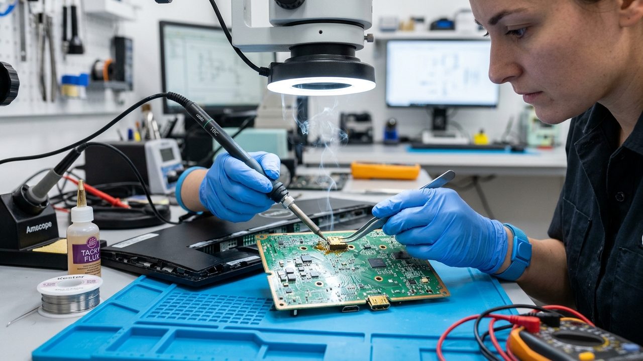
Repairing a damaged HDMI port on a computer monitor is an intricate micro-soldering procedure requiring specialized tools, thermal management expertise, and microscopic precision. Unlike desktop motherboards where components can easily be reached, monitor video scaler boards are buried inside ultra-thin chassis sandwiched between fragile liquid crystal panels and high-voltage power inverters.
Phase 1: Safe Teardown & Panel Protection
Technicians place the monitor face-down onto a specialized high-density ESD foam mat to prevent scratching the anti-glare polarization layer of the LCD/OLED panel. Using ultra-thin plastic pry spudgers, the bezel snaps are released around the perimeter. The internal video scaler mainboard is disconnected from the delicate LVDS (Low-Voltage Differential Signaling) or eDP ribbon cables that drive the display matrix. One wrong slip with a metal tool can permanently crack the glass substrate, rendering the entire display panel useless.
Phase 2: Desoldering the Defective Connector
An HDMI port is anchored by four heavy structural through-hole ground legs soldered into multi-layer copper ground planes that act as massive heat sinks, alongside 19 microscopic surface-mount signal pins. Removing the port safely without overheating adjacent microchips requires precision thermal management:
- Low-Melt Alloy Application: Technicians apply specialized low-temperature bismuth-based desoldering alloy (melting point ~138°C) to all anchor legs and signal pins using high-activity rosin-free tacky flux. The low-melt alloy mixes with factory lead-free solder (which melts at a high ~217°C), dramatically lowering the overall melting point.
- Controlled Hot Air Rework: Using an automated hot air rework station fitted with a concentrated nozzle and a bottom preheating plate set to 150°C, heat is applied evenly across the underside of the PCB. Once the solder liquefies simultaneously across all 23 contact points, the damaged port is lifted straight off the board with anti-static precision tweezers without applying any lifting force that could rip delicate copper traces.
- Pad Preparation: The remaining solder is cleaned using copper desoldering braid wick and 99% isopropyl alcohol until the copper landing pads are mirror-smooth and coplanar under an inspection stereo microscope.
Phase 3: Installing the OEM Replacement Receptacle
The technician selects a precision-matched OEM HDMI connector matching the exact pin pitch, shell ground tab offsets, and height profile of the original board:
- Fresh leaded or SAC305 lead-free solder paste is applied across the 19 SMD pads.
- The new connector is positioned with microscopic alignment under 20x to 40x optical magnification.
- Using a fine micro-pencil soldering tip (such as a 0.2mm bent conical or mini-hoof tip) and drag-soldering technique, each pin is bonded individually, creating concave, shiny, crack-free solder fillets.
- The four heavy through-hole mechanical anchor tabs are flooded with high-strength structural solder to ensure the port can withstand hundreds of pounds of insertion torque.
Phase 4: Multimeter Diode-Mode Continuity Testing
Before reassembling the monitor chassis, technicians perform comprehensive electrical validation using a digital multimeter in Diode Mode connected to a breakout breakout board plugged into the newly soldered HDMI receptacle. In diode mode, the red positive probe is placed on chassis ground while the black negative probe tests each of the 19 pins:
- All high-speed TMDS differential data and clock lines (Pins 1, 3, 4, 6, 7, 9, 10, 12) must display a uniform forward voltage drop between 0.450V and 0.650V. An
OL(Open Loop) reading indicates a broken solder joint or severed trace; a reading below0.100Vindicates a short circuit to ground or blown ESD protection diode. - Ground shield pins (Pins 2, 5, 8, 11) must read exactly
0.000V, confirming flawless ground continuity. - DDC lines (Pins 15 and 16) must show identical voltage readings, confirming communication with the EDID EEPROM chip.
The Cryptographic HDCP Handshake: Why Streaming Services Black Out on Damaged Ports
A peculiar symptom that frequently baffles monitor owners occurs when standard computer desktop navigation, spreadsheets, and YouTube videos display normally, but opening streaming services like Netflix, Disney+, Amazon Prime Video, or 4K Blu-ray playback instantly turns the screen pitch black or flashes an HDCP Error 020 error code.
HDCP (High-bandwidth Digital Content Protection) is an encryption protocol developed by Intel to prevent digital media from being pirated between video sources and screens. Modern 4K and HDR content mandates HDCP 2.2 or HDCP 2.3 compliance. For HDCP authentication to succeed, high-speed bi-directional cryptographic keys must be continuously exchanged over the DDC channel (Pins 15 and 16) without packet corruption. If physical port wear introduces micro-resistance, jitter, or capacitance anomalies onto these lines, standard unencrypted video can still pass through, but the cryptographic cipher exchange fails, causing media players to shut down video playback immediately. Precision hdmi port repair restores the signal integrity required for pristine HDCP cryptographic handshakes.
Handling Torn Circuit Traces: Micro-Jumper Reconstruction
When an HDMI cable is yanked violently, the structural anchors often hold while the surface-mount pins rip clean off the board, tearing away the paper-thin copper foil traces (measuring just 0.035mm thick) adhered to the FR4 fiberglass substrate. In an untrained shop, a board with torn pads is declared "unfixable". At an advanced micro-soldering facility, technicians reconstruct the destroyed circuits:
Microscopic Trace Reconstruction Protocol:
- Trace Scraping: Under high-power optical magnification, the technician uses an ultra-fine surgical scalpel blade to gently scrape away the protective green solder mask coating adjacent to the torn pad, exposing bare shiny copper trace (often only 0.1mm wide).
- Micro-Jumper Wire Bonding: A microscopic strand of insulated polyurethane-coated 0.02mm enameled copper wire (thinner than a human hair) is soldered directly to the exposed trace, looped carefully to form a replacement solder pad, and anchored to the corresponding replacement HDMI pin.
- UV Curable Solder Mask Curing: The reconstructed micro-jumpers are coated with industrial ultraviolet-curable dielectric solder mask resin. Exposing the resin to a high-intensity UV lamp polymerizes the compound in seconds into an rock-hard structural insulator, permanently bonding the new traces to the fiberglass substrate and protecting them from mechanical vibration and oxidation.
HDMI Version Standards: Bandwidth, Refresh Rates & Compatibility
When replacing a broken HDMI port, utilizing the correct port revision is vital. Installing a legacy HDMI 1.4 port onto a modern high-refresh-rate gaming monitor will severely bottleneck its operational capabilities:
| HDMI Version | Max Raw Bandwidth | Max Supported Resolution & Refresh Rate | Key Modern Features |
|---|---|---|---|
| HDMI 1.4b | 10.2 Gbps | 1080p @ 144Hz / 1440p @ 75Hz / 4K @ 30Hz | Basic 3D video support, Audio Return Channel (ARC), 8-bit color. |
| HDMI 2.0b | 18.0 Gbps | 1080p @ 240Hz / 1440p @ 144Hz / 4K @ 60Hz | HDR10 static metadata, 32 audio channels, 21:9 ultrawide aspect ratio support. |
| HDMI 2.1a | 48.0 Gbps | 4K @ 144Hz–240Hz / 8K @ 60Hz / 10K @ 120Hz (DSC) | Fixed Rate Link (FRL), Variable Refresh Rate (VRR), Auto Low Latency Mode (ALLM), Enhanced ARC (eARC), Dynamic HDR. |
Professional repair facilities always source exact OEM replacement ports rated for the full electrical bandwidth and high-frequency shielding standards of your specific display.
Monitor Repair vs. Replacement: The Financial & Environmental Equation
Does it make financial sense to pay for an hdmi port repair, or should you discard the screen and purchase a replacement? The answer depends on your monitor's category and value tier:
| Monitor Class & Type | Replacement Cost New | Typical Port Repair Cost | Financial Recommendation |
|---|---|---|---|
| Entry-Level Office Monitor (21"-24" 1080p 60Hz) | $80 – $120 | $75 – $100 | Replace or Use Adapter: Repair cost approaches full replacement value unless utilizing alternative ports. |
| Mid-Range Gaming Display (27" 1440p 144Hz–170Hz) | $250 – $400 | $95 – $135 | Strongly Recommend Repair: Saves $150 to $275 while preserving your calibrated gaming display. |
| High-End 4K, OLED, or 240Hz Gaming Monitor | $650 – $1,200 | $110 – $165 | Definite Repair: Incredible ROI—restores a flagship display for less than 15% to 20% of replacement cost. |
| Ultra-Wide Curved / Professional Studio Display (34"-49") | $800 – $1,800+ | $120 – $180 | Definite Repair: High-end panels are difficult and expensive to replace; board-level port repair is overwhelmingly superior. |
Beyond direct financial savings, repairing an existing monitor prevents toxic electronic waste (e-waste). Display panels contain complex optical diffusion films, rare-earth phosphors, mercury vapor backlights in older models, and heavy plastics that take centuries to decompose in municipal landfills.
Temporary Workarounds: Adapters, DisplayPort & USB-C Alt-Mode
If you cannot immediately bring your monitor in for a professional bench repair, you may be able to keep working using alternative digital video interfaces already present on your monitor:
- Switch to Native DisplayPort: Nearly all mid-tier and high-end monitors feature at least one full-size DisplayPort (DP) connector. DisplayPort offers even higher raw bandwidth than HDMI 2.0 (DP 1.4 delivers 32.4 Gbps) and supports identical or superior refresh rates, G-Sync, and FreeSync. If your PC has a DisplayPort output, simply switching from an HDMI to a DisplayPort cable bypasses the broken port entirely at zero repair cost.
- Active DisplayPort to HDMI Adapters: If your monitor's only HDMI port is broken, but it has an available DisplayPort, you can connect an HDMI video source (such as a gaming console or streaming stick) using an Active HDMI-to-DisplayPort Converter. (Note: standard passive cables only work from DP source to HDMI screen, not the reverse).
- USB-C DisplayPort Alternate Mode (Alt-Mode): Modern productivity monitors frequently incorporate a USB Type-C port capable of carrying simultaneous video signals, USB data hub connections, and 65W–90W Power Delivery. Connecting your laptop via USB-C provides flawless display output while bypassing the damaged HDMI port completely.
Preventative Care: 5 Ways to Protect Your Display Ports from Physical Strain
Once your monitor has been successfully repaired, implement these five preventative strategies to protect the new port from recurring stress:
- Install 90-Degree Right-Angle Adapters: If your monitor's rear ports point straight outward toward a wall, plug in a low-profile 90-degree or 270-degree right-angle HDMI adapter. This redirects cable weight downward parallel to the chassis, eliminating 90% of leverage-induced torque on the internal PCB solder joints.
- Secure Cable Strain Relief: Fasten your HDMI and power cables securely to the monitor stand or desk arm using Velcro straps, leaving a gentle slack loop between the anchor point and the port. If someone trips over the cable, the tension is absorbed entirely by the monitor stand, rather than shearing the port off the motherboard.
- Avoid Cheap, Excessively Rigid Cables: Extremely thick, stiff nylon-braided cables look impressive but transmit tremendous mechanical force when bent. Opt for ultra-flexible, high-grade silicon or PVC-jacketed certified HDMI cables that bend effortlessly without exerting continuous tension against the port receptacle.
- Use Port-Saver Extension Pigtails: In environments where laptops or consoles are frequently plugged and unplugged (such as conference rooms or gaming battle-stations), attach a short 6-inch HDMI "port-saver" extension lead. All repeated insertion wear and tear happens to the replaceable $7 dongle, leaving the monitor's internal female port untouched.
- Never Force an Unaligned Connector: Always visually confirm connector orientation before inserting, especially when reaching behind a display in low light. If resistance is met, stop immediately—never jam, wiggle, or force an HDMI connector into place.
Why Choose DC Phone Repair for Your Monitor Board Repairs
While many general repair shops refuse to open computer monitors due to the fragile nature of display panels, DC Phone Repair houses dedicated micro-soldering labs equipped with industrial stereo microscopes, programmable infrared preheaters, and precision temperature-controlled micro-irons:
- Precision Board-Level Expertise: We don't just swap whole expensive boards; we repair components down to the individual trace, pin, and SMD diode level.
- OEM-Grade Replacement Components: We stock genuine high-spec HDMI 2.0 and HDMI 2.1 receptacles designed for maximum mechanical durability and high-frequency digital signal integrity.
- Comprehensive Pad Reconstruction: Even if your port was ripped violently off the board with multiple torn copper traces, our micro-soldering specialists can reconstruct missing pads using enameled micro-jumpers and UV dielectric mask.
- Rigorous Signal & Stress Testing: Every repaired monitor undergoes full resolution, high-refresh-rate (120Hz/144Hz/240Hz), and color-gamut validation before leaving our repair bench.
Need Fast & Reliable Device Repair in Washington, DC?
Don't let a cracked screen, dying battery, or faulty charging port slow you down. Our certified technicians provide same-day diagnostics and repairs using premium replacement parts backed by our comprehensive warranty.
Phone: (202) 478-4799 | Open Daily: 10:00 AM - 10:00 PM